


|
|
|
|
Mustang II Construction Pics
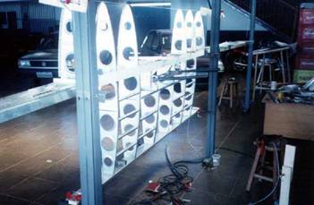
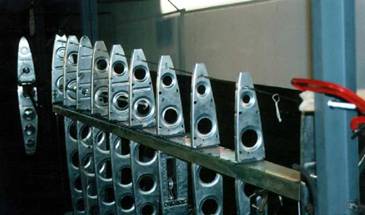
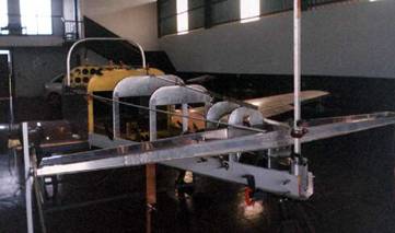
Photo 1 Photo 1 - For the center section and wing construction, we have made a steel jig, with four 7' tall separated posts , and the three spars support, totalizing almost the same size of aircraft´s wing span. Note the adjusted and leveled center section ribs. By the way, the leading edge alignment has to be perfect, because Naca 64a212 airfoil is laminar flow, so we would prevent high stall speeds .
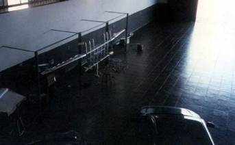
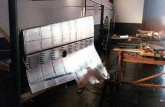
Photo 2 Photo 2 - The steel jig was leveled in all the directions and fixed on the wall for bigger rigidity. Note that the main wing spars were added and attached to center section, and is clearly visible the 5º wing dihedral.
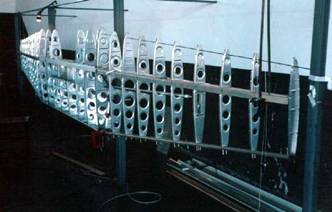
Photo 3 Photo 3 - The center section and wing ribs alignment. The main basic used tools were a spirit level and a plumb bob. Note that we used a 3/16" O.D. steel bar for leading edge alignment, using the ribs reference holes. In my opinion, this kind of construction at once became an easier and precise building way.
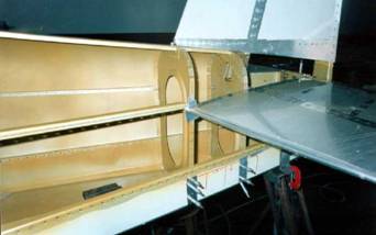
Photo 4 Photo 4 - Perhaps the biggest project challenge. The wet wings construction, or integral tanks. Note the PRC sealed spar capstrips and the capacitance fuel probe installation, wich consists of an isolated aluminum tube.
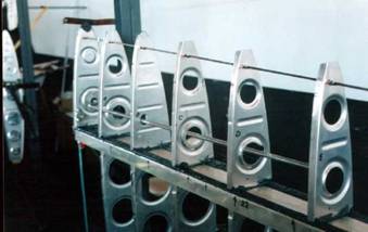
Photo 5 Photo 5 - Four ½" holes and two small cut in its bases were made in each wing rib , for the wing internal air and fuel flow.
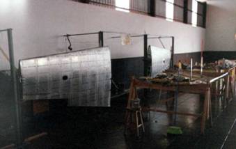
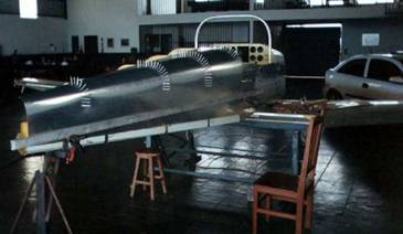
Photo 6 Photo 6 - With riveted and closed leading edges (an extremely difficult operation), the rear wing skins riveting was initiated. Note the inspection window, located in the aileron bellcrank area
Photo 7 Photo 7 - Both wings are closed. Note the cutt aileron place , that had been built later.
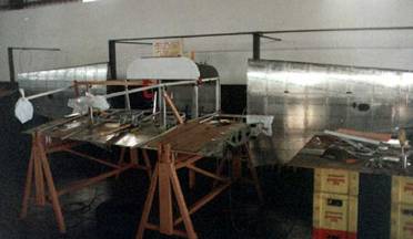
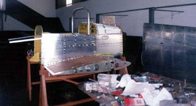
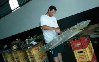
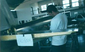
Photo 8 Photo 8 - After completing the center section, we have put it horizontally over saw horses, so we began to build the forward fuselage. Note that we had put the firewall, the blank instrument panel, and fuselage main stringers.
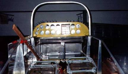
Photo 9 Photo 9 - In the front of fuselage, he have adjusted the main tank (behind the instrument panel), the flap handle, and adapted Piper Arrow seats with tracks. The original seats are fixed in the plans, so we opted to make an adjustable set. Some builders have installed another great mod, the cessna 150 seats. The roll bar, or windshield support, was affixed on the place, but was not yet with correct height. This adjustment had to be made later, when the seats became completed .Note that the instrument panel holes had been made, with my own design, like the following layout.
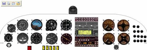
Figure 1 - Mustang II instrument panel layout, made from specific software . This panel will have basic flight instruments, Gmeter, engine instruments, avionics, switches and right side circuit breakers , with similar Mooney design.
Photo 10 Photo 10 - Clecoed forward fuselage lateral skin.
Photo 11 Photo 11- The nicknamed "Kiko" A&P, adjusting the firewall and engine mount.
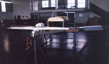
Photo 12 Photo 12 - The tailcone construction beginning. It has flat belly, and does not require complicated jigs, so we just used some saw horses to place it. We have attached the wings for an accurate tailcone centering. Note that the horizontal stabilizer structure was placed and adjusted.
Photo 13 Photo 13 - Fuselage bulkheads alignment.
Photo 14 Photo 14- Tailcone right skin ready to be riveted.
Photo 15 Photo 15 - Horizontal stabilizer being clecoed and chemical threated for the riveting procedure. Note our beer table base.......
Photo 16 Photo 16 - Empennage detail. It has a very strong and rigid structure. With a 200 knots, the flutter must be prevented. So its important to use counterweights and thick skins that solve this problem perfectly.
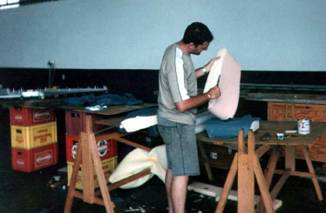
Photo 17 Photo 17- Piper type seat foam.
Photo 18 - Tailcone riveting. Kiko is there inside bucking the rivets
Continues in Pics 2
.
|